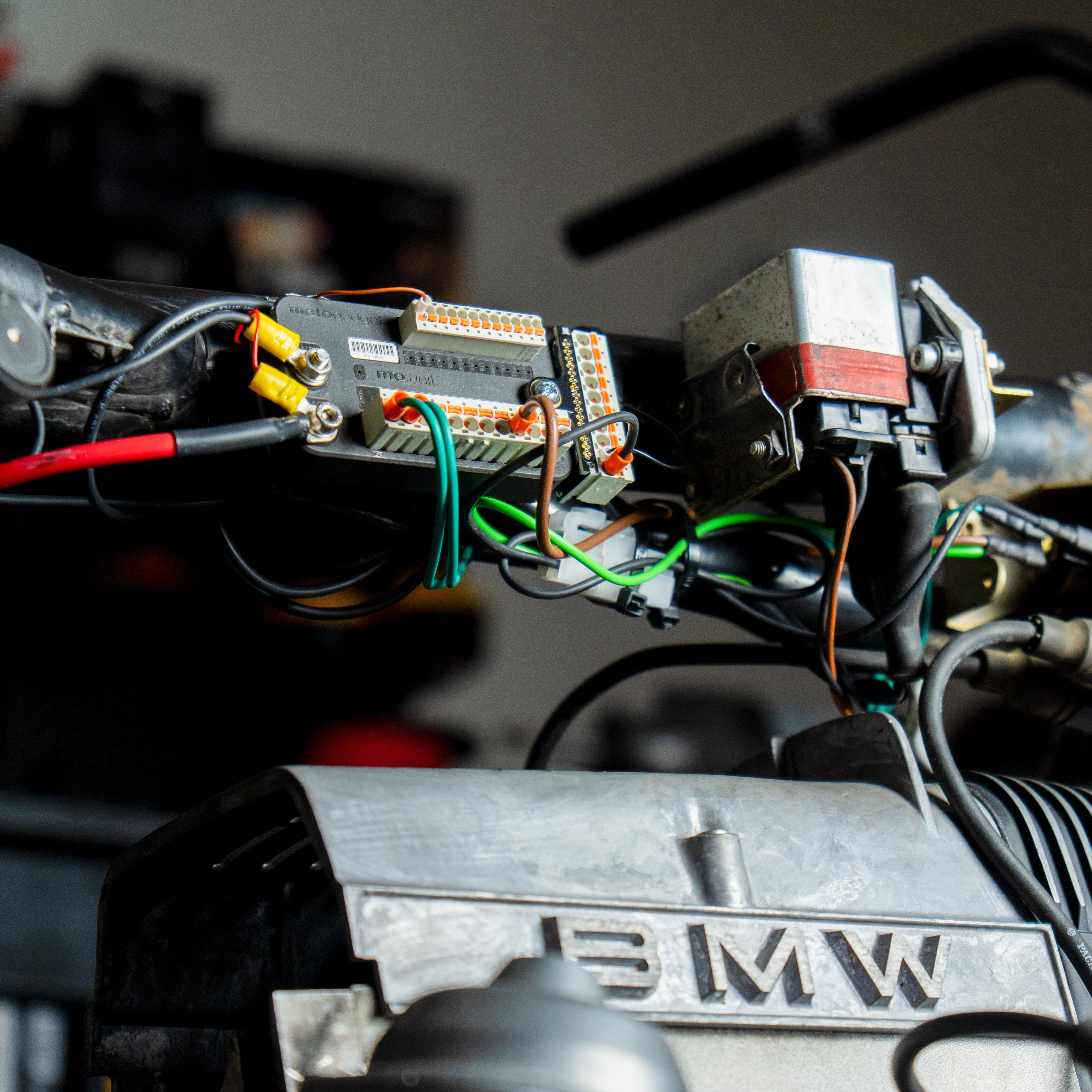


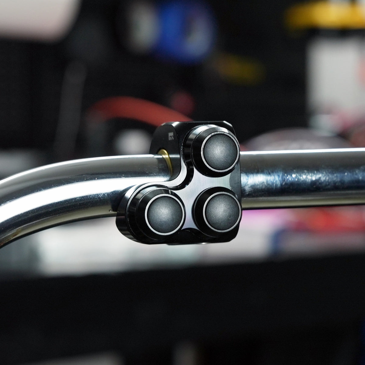
The mo.unit blue is installed. The motorcycle starts. But right now you’re still controlling it with a makeshift setup: one cable plugged into the input, the other end held against ground—it works, but it’s not a permanent solution. Time for the proper solution: a switch on the handlebars.
This post is related to Part 5 of the motogadget YouTube series:
This is Part 5 of our comprehensive mo.unit blue installation series. In Part 1, we covered the complete motogadget shopping list and project overview. In Part 2, we prepared the wiring harness and created the wiring diagram. In Part 3, we learned the basic techniques for connecting motorcycle wires. In Part 4, we installed and wired the mo.unit blue and started the motorcycle. Now let’s get the controls set up properly: install the motorcycle switches and connect them to the mo.unit.
By the end, you'll have both handlebar-mounted shifters installed, wired up, and working—and you'll understand why grounding the handlebars requires a bit more finesse than you might think. But we'll get to that in a moment and walk you through it step by step.
What we'll do in Part 5:
- An explanation of the two types of motogadget mo.switches and when to use each one
- An In-Depth Look at Handlebar Mass—Why It's More Complex Than Just "Metal = Mass"
- Installing and Wiring the mo.switch basic (without LED)
- Installing and Wiring the mo.switch basic LED
- Connect both to the mo.unit blue inputs
- Troubleshoot the aux1/aux2 output settings in the mo.ride app if your lights don’t… light up
The two types of mo.switches
motogadget manufactures two main categories of handlebar switches:
- mo.switch basic / mo.switch plain: No LEDs. No pre-wiring. Simple, sleek, and fully customizable in terms of cable routing and colors.
- mo.switch basic LED / mo.switch pro LED: Similar design, but with an LED ring around each button. Comes pre-wired from the factory—you simply run the cable bundle to the mo.unit. Plus an extra cable: a red positive cable to power the LEDs in the switch.
The switches themselves work the same way regardless of style. They're ground-controlled — pressing a button completes a circuit to ground, the mo.unit sees the signal and triggers the output. (Again, that extra 12v wire is just to power the lights on the mo.switch LED).
Mass:
This section primarily applies to the non-LED models
Before we mount anything, we need to talk about grounds — specifically handlebar grounds — because this is where most mo.switch problems come from.
Your battery negative runs to the engine block or to the frame. The engine is bolted to the frame, and vice versa. So the frame is a ground. Any bare metal surface that traces back to that cable is a ground. In theory, mount your switches to the handlebars, and you've got a ground.
But in practice, it's not that simple.
The triple tree problem
Follow the path your handlebar “ground” has to take: handlebar → triple clamp → steering stem → steering bearings → frame neck.
Those bearings are often the constriction point, packed with grease and rolling on steel balls. Grease and intermittent metal contact are not good conductors. This is the weakest link in handlebar grounding on almost every motorcycle.
How to check your handlebar ground
With that being said, you can still use your handlebars as a normal ground, so long as you confirm that it has low resistance. Set your multimeter to resistance (ohms). Touch the black probe to your battery negative terminal and the red probe to your handlebars. Slowly rotate the bars left to right, lock to lock, while watching the reading.
motogadget specification: less than 3 ohms from the handlebars to the battery negative terminal, to bypass a dedicated ground wire.
Pro tip: Check resistance through the full steering range, not just the center. Bearing contact changes with steering position — you might pass at center and fail at full lock.
Powder coat is a ground killer
Chrome handlebars? Probably fine. Black powder-coated handlebars? The coating adds resistance everywhere the switch housing clamps onto. You may pass the resistance check with chrome bars and fail immediately with coated ones. Factor this in when you're choosing bars.
The solution if you fail the test
Run a dedicated ground wire from the negative terminal of the battery, or from a very solid grounding point on the frame. Then, run the wire up to the handlebars and connect to one of the grounding spots on the mo.switch body. Your handlebars now have a strong ground connection, meaning you can ground the other side without another grounding wire, so long as you’re using metal bars. If you had plastic or carbon fiber bars or clipons, you would have to run a dedicated ground wire to each switch body.
mo.switch basic: Design and Installation
The box contains:
- Switch housing
- Push-button switch
- Spacer Ring (for ⅞" handlebars)
- Various wire end ferrules and screws
The switch body has two terminals per button. One side gets grounded, the other runs a signal wire to the mo.unit input. Instead of running a separate ground for every button, motogadget includes a ground daisy chain — a ring terminal with three short wires that shares one ground across all buttons. Install a ferrule on each wire, insert one into each button's ground terminal, done.
Then add your three signal wires (one per button) to the remaining open terminals. These are the wires that run to the mo.unit inputs — start, turn left, turn right, horn, or whatever you're assigning.
mo.switch basic: Installation
- Step 1: Plan your position before you drill. Mock up everything that goes on the handlebar — throttle tube, brake lever, grip. Find a natural position for your thumb and confirm button placement before you mark anything.
- Step 2: Drill the entry hole for the wires to head to the mo.unit
- Step 3: Smooth the hole. Seriously. This is not optional. The raw, drilled edge is sharp enough to cut through wire insulation in hours of vibration. File or sand both the inside and outside of the hole until it's completely smooth. No burrs, no sharp edges.
- Step 4: Mount the switch housing. Add the spacer ring if your bars are 7/8". Slide the housing on, align the hole in the spacer with your drilled entry point, and tighten the clamping bolt. Install the grub screw — this drives into the handlebar and grounds the housing directly to the bar. Tighten it enough to bite in, not enough to strip it.
- Step 5: Feed the wires into the entry hole and fish them out at your exit point (drill a second hole at center, ideally on the front side facing the headlight). Threading a stiff wire in from the exit end and taping your switch wires to it makes this manageable. It's never fast, but it's not impossible either.
- Step 6: Drop the switch buttons in, and run the mounting screw through the bottom.
Pro Tip: Make sure your wires have enough play/slack that the bars can go full lock in both directions without pulling tight or pinching the wires against the tank. Check this before you cut your wires to length.
mo.switch basic: Wiring to the mo.unit
Add ferrules to the end of each signal wire. Insert them into the corresponding mo.unit inputs — start, headlight, turn left, turn right, or whichever inputs you're using. The input label positions are in the mo.unit manual if you can’t read them off the unit.
If you haven’t done so already, run your dedicated ground wire (if you're using one) to the battery negative terminal.
To confirm everything works without outputs connected: turn the mo.unit on, press each button, and watch the corresponding input indicator light on the unit. If the input lights up, the switch is working.
mo.switch basic LED: Differences
The LED version comes pre-wired. Terminal screws are not required—but wire end caps can still be attached if needed. Simply route the cable harness and connect it.
What you'll get:
- Signal cables (one per button)
- A black ground wire
- A red positive cable for the LEDs
The switches still work the same way — ground-controlled signals. The extra red wire just powers the LED rings.
Identifying which wire controls which button: use a multimeter in continuity mode. Ground one probe, touch the other to a signal wire, and press each button until you hear the beep. Label as you go.
mo.switch basic LED: Wiring to the mo.unit
Connect the ground wire to the mo.unit ground terminal if you’re using one, or any solid ground. Connect the three signal wires to their input, making sure to use wire ferrules just as before.
For the red power wire, you have options:
- AUX1 or AUX2 – lets you control the LEDs with a pushbutton (useful if you want to be able to turn them off). AUX2 is recommended because the IGNITION is turned off when the KILL switch is activated or the side stand (STAND) is down—the pushbutton lighting would then also turn off.
- IGNITION — LEDs come on with the bike, go off with the bike, no button needed. Note: When the KILL switch is activated or the side stand is down, the IGNITION turns off, which also turns off the button illumination.
Whatever you choose, make sure the output is set to come on when the bike is running and off when it isn't. You don't want LEDs draining the battery.
If your LEDs don't turn on: mo.ride app output settings
This trips up a lot of people. You've connected everything correctly, you press the AUX1 button, nothing happens. The input light blinks on the mo.unit. The LEDs stay off.
- Open the mo.ride app → settings (gear icon) → mo.unit settings → Output AUX1.
- The default setting is often "Taillight." Change it depending on what you want:
- Switch at AUX1 — LEDs on while button is held, off when released (momentary)
- Button at AUX1 — press to turn on, press and hold to turn off (toggle)
- Activate with ignition—always on when the bike is on; no button required
- Select the one that matches the switch behavior you want, press OK, and test it. It's easy once you know where to look.
What happens next
Next, we'll wire up what these inputs actually control—the outputs. Lights, the horn, and everything else.
In the meantime, you can tidy up the handlebar wiring, check the cable length at full lock, and make sure nothing is rubbing against the gas tank or frame.
- Jacob Baldry, for motogadget