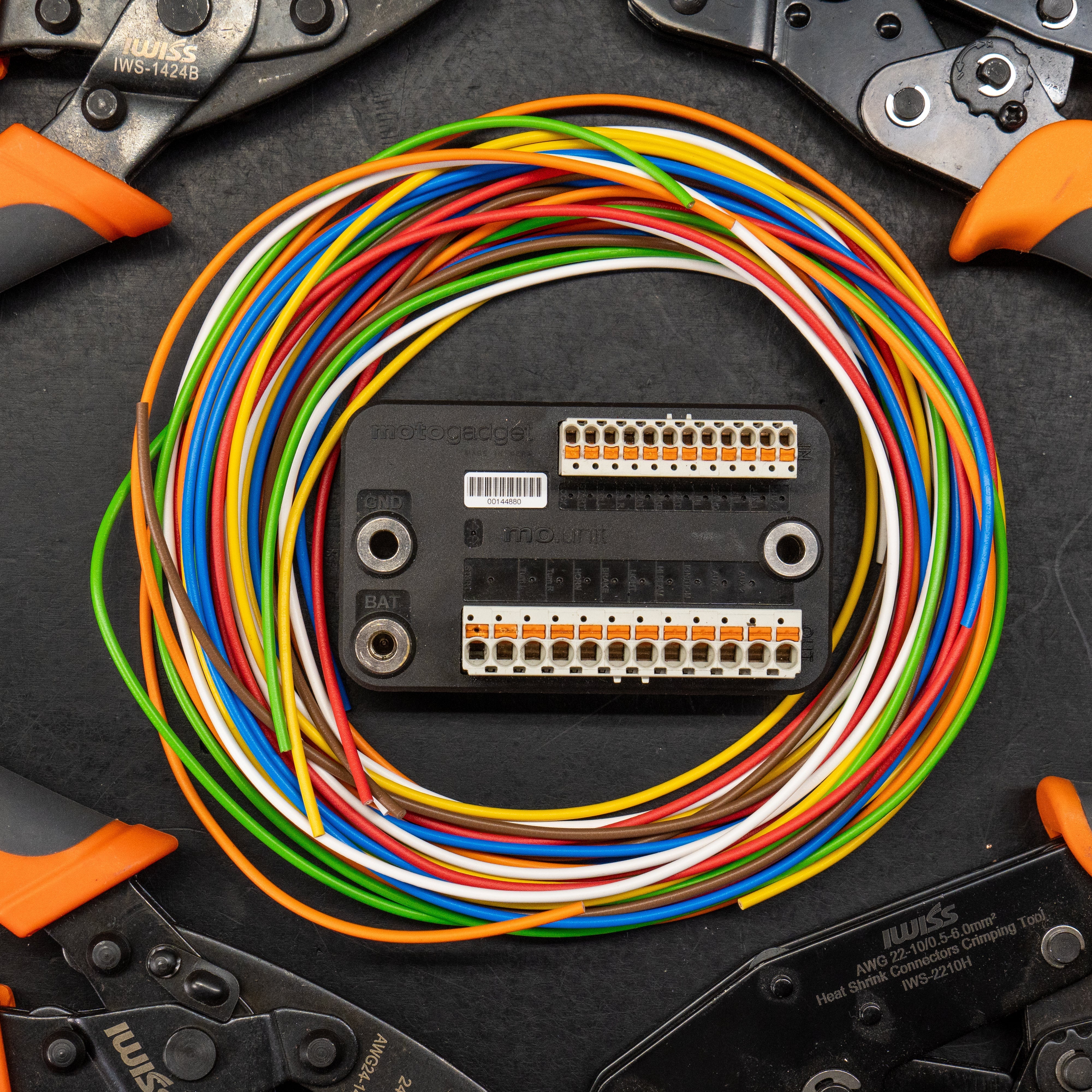


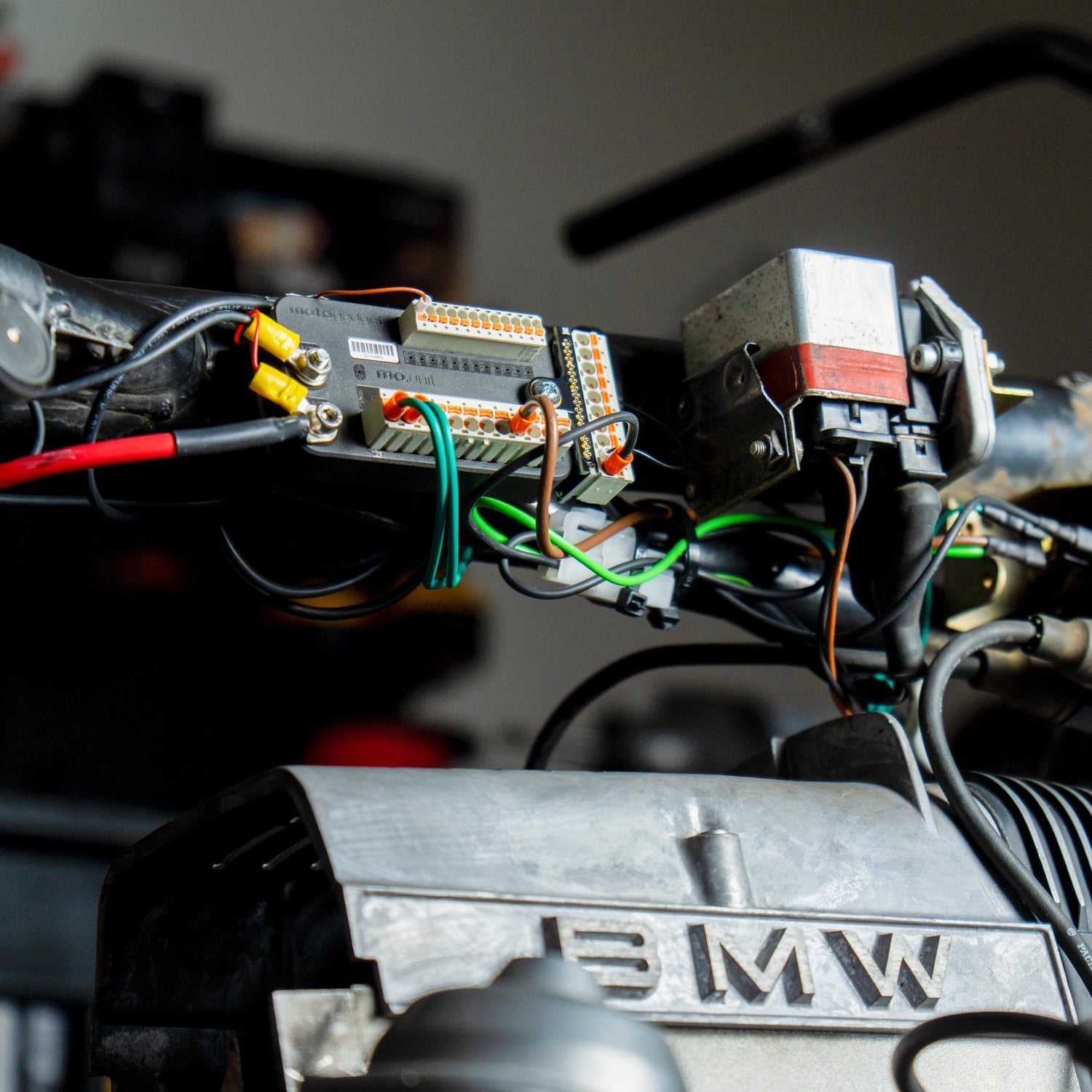
So you’ve got your mo.unit blue in hand and you’re motorcycle (relatively) ready to receive it — what’s the first thing to plug in? Let’s talk about it.
This is Part 4 of our comprehensive mo.unit blue installation series. In Part 1, we covered the complete motogadget shopping list and project overview. In Part 2, we prepared the wiring harness and created the wiring diagram. In Part 3, we learned the basic techniques for connecting motorcycle wires. Now it’s time to get down to business: the motorcycle control unit is going into the bike.
This post is based on the fourth installment of our motogadget installation series on YouTube:
What We'll Cover in Part 4
- Bench test of the mo.unit blue, so you can fully understand how it works before installing it on your bike
- Walk through the wiring diagram after stripping everything non-essential
- Mount the mo.unit blue and connect battery power and ground
- Install the mo.lock NFC as the ignition switch
- Connect the 12V switched ignition and starter solenoid
- Starting a Motorcycle
The Benchmark Test: How the mo.unit blue Really Works
Before we even touch the motorcycle, let's make sure we understand what we're building. Here's the whole system in four parts:
- The battery— supplies power to the mo.unit blue
- The mo.lock NFC — tells the unit when to turn on and off
- Input signals – we’ll use ground-controlled switches to send input signals to the mo.unit (turn left, turn right, start, etc.)
- Output Power – once the mo.unit knows what to do (due to your input signal), it sends power out via the output side to the designated destination.
The key thing to understand about the mo.switch inputs: there's no 12V power running through them. They're just completing a circuit to ground — similar to how a continuity meter works. The mo.unit handles the power. The switch just says "go." That's what makes this system so much more reliable than old-school switches with full voltage running through them.
Pro Tip: Practice this on the bench before you're buried inside a headlight bucket. Once you see it work with a handful of wires in your hand, the whole system “clicks”.
The Wiring Diagram: What's Left
After stripping the harness in part two of this series, here's what remains:
Keep:
- Alternator, regulator/rectifier, stator
- Ignition control unit
- Starter motor and solenoid
- Oil pressure switch, neutral switch
Removed and replaced by the mo.unit blue:
- Original wiring harness (controls, relays, switches, dashboard - The latter can be reused, if desired.)
- Headlight relay
- Turn signal relay
- Original ignition switch (can optionally be reused)
- Fuse Box
As previously discussed: The mo.unit does not replace the charging or ignition system.
A feature unique to BMW
For the alternator to charge correctly on BMW two-valve models (R45, R60, R65, R70, R80, R90 and R100), the resistance provided by the original charge warning lamp is essential.
If the original warning lamp is removed, a resistor with the appropriate rating must be installed in its place.
This resistor must be connected between the mo.unit’s IGNITION output and the blue wire leading to the voltage regulator.
Golden Rule: Do your research on your specific motorcycle. There’s almost always some quirk that isn’t covered in any video.
Installing the mo.unit blue
For this stage of the build, the mo.unit blue is bolted onto a steel plate that’s tack-welded to the frame. Not pretty, but fine for now. The final build will have a properly welded, powder-coated plate — but at this point, the goal is just to get everything working.
A few things that matter regardless of how you mount it:
- The mounting plate should be conductive and welded (or bolted) solidly to the frame so it acts as a ground
- When powder coating, leave the threads exposed (for ground connection)
- For steel, use grease if necessary
- Check the clearance between the tank and the seat before deciding on a position
- The ground bolts on the mo.unit run through the plate — so a solid metal mount means a solid ground connection
Connect the power supply
Cable specifications from the mo.unit manual:
- Positive (BAT): 6mm² cross-section minimum (the Ultimate Builder Kit includes an 8 gauge / ~8mm² fused cable — slightly over spec, which is great)
- Ground: 1.5mm² cross-section (roughly 14 gauge)
Important: Don't install the fuse until everything is connected and you're ready to test. A live fused cable touching bare metal will arc. A live, grounded cable that comes into contact with bare metal will cause a short circuit—resulting in intense sparks, a risk of burns, and possibly damage to the mo.unit or other components.
Connect the positive first to the BAT terminal (threaded, closed hole — use the small bolt that comes with the unit, and add medium-strength thread locker on the final build). Ground runs through the mounting plate bolts — but leave the nut loose for now, because more ground connections are coming.
Install mo.lock NFC
There are three wires:
- Black → Ground
- Red → positive (constant)
- Brown → LOCK input on the mo.unit blue (this is your switched 12V)
That's it. When you pass the NFC tag over the lock, the mo.unit turns on. Pass it again, it turns off. The motorcycle now has a keyless ignition system with no moving parts.
One Hot Wire
Ok, so we said all the inputs are ground controlled — which is mostly true, except the one brown wire running from the mo.lock NFC to the lock input. This helps so that the mo.unit can work with more OEM-style key switches that push 12v switched power to the bike to turn on. Just plug in the brown wire and focus back to ground-controlled inputs.
Wiring the Ignition and Starter
Two remaining connections to fully integrate the mo.unit blue:
Positive Ignition
The IGNITION output is activated when the mo.unit is turned on and provides positive ignition voltage to the ignition system and the ignition coils. The motorcycle is now ready to be started electrically.
Starter solenoid
The mo.unit has two START outputs. On this BMW, both connect to a single terminal on the starter solenoid via a double-male to single-female spade adapter. One wire per output, both feeding the same solenoid terminal. This is just so that the mo.unit can pump out enough juice without breaking a sweat.
The maximum current rating of 30A is important here. Therefore, the original starter relay—or, in the case of BMWs, at least the solenoid switch—must remain installed. This is one of the most critical aspects of the wiring. Incorrect wiring at this point can quickly lead to overheated wires or even an electrical fire.
Pro Tip: There's a small built-in delay before the starter kicks. Don't panic if it doesn't fire instantly. That delay is intentional — it prevents accidental starts.
First start
With just a few connections made to the mo.unit blue — positive, ground, mo.lock, ignition, two start outputs — the system is “complete”.
Fuse goes in. NFC tag to the lock. Green light.
Make sure both wires from the START output terminals are securely connected to the relay or solenoid switch.
It runs.
Before you do this, know how to shut it down:
- Pass the NFC tag again — turns the unit off
- Pull the 40 amps fuse — kills power
- Keep a fire extinguisher nearby and open a garage door
Verifying the charging system
Once the engine is running and up to around 3,000–4,000 RPM, put a multimeter on the battery. You want to see 13+ volts. If you're sitting at 12.6V or below, check your regulator/rectifier connections. Your specific service manual will tell you the exact RPM range where charging should kick in. What we’re doing here is confirming that we didn’t break the connection from the charging system to the battery. If the battery doesn’t charge with higher RPMs, we missed something.
What happens next
In part 5, we move up to the handlebars. Both versions of the mo.switch — the pre-wired LED models and the standard versions you wire yourself — get installed and connected to the mo.unit inputs.
In the mean time, clean up your wiring. If you've confirmed your mo.unit location, finish the welds. Route your existing wires and start getting things organized before we add more at the bars.
- Jacob Baldry, for motogadget